Progression has progressed with progress! Despite the setbacks with the incorrect bolt pattern on the axles, I was able to get the rear set up and all calculations have been run, double run, and triple run with triangulatory and squarity preserved. I originally was going to design my own rear set up using torsion bars like the factory had and at the last minute just decided a 4-link was a better way to go. Not knowing about something leads me to searching for people smarter than I am to either learn by osmosis or the sponge effect and soak up all of their knowledge. While the previous got me through college using my textbooks, I cant see calling a rep from a chassis shop and asking if we can touch craniums for a couple days.

Besides being a pain to coordinate, it sounds creepy. Geeze, where was I? OK, moving on
..
It seems the off road crowd loves the 4-link set up. Check out any monster truck racing scene and youll see it. Rock crawlers sport them too. Theres a lot going on back there which I learned really quickly. This is such a fun project since its making me learn a whole new everything in regards to cars that I didnt know before. Calculations a plenty!!!
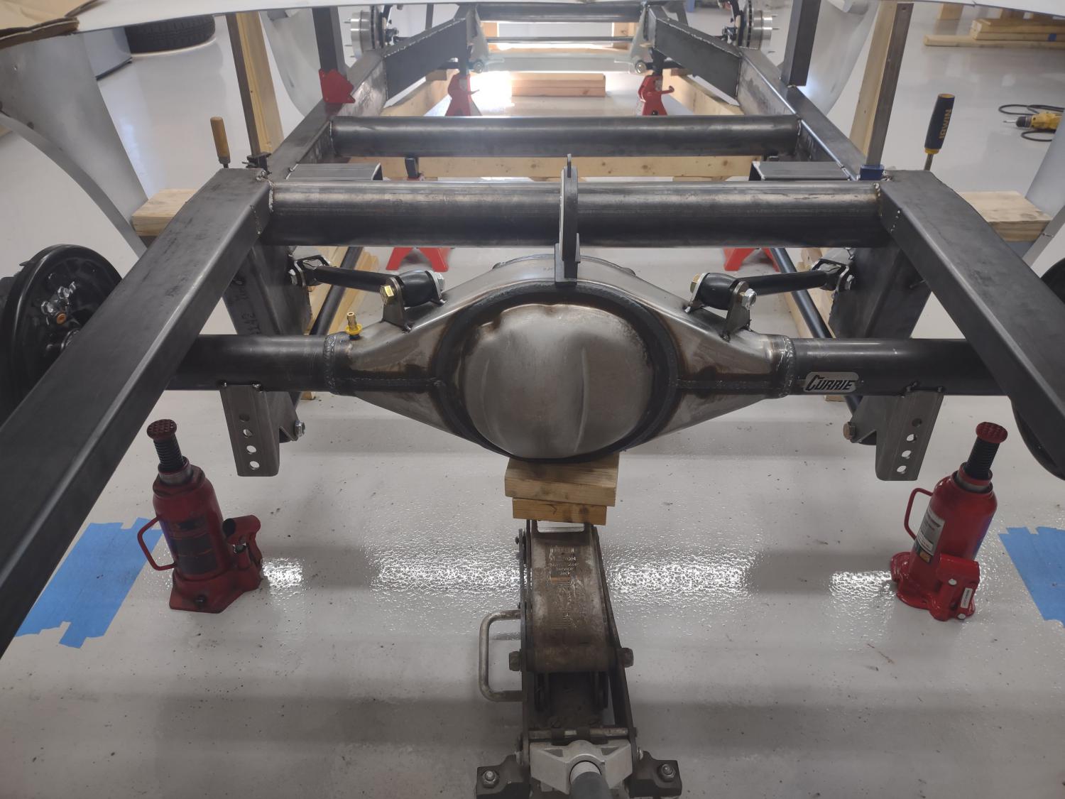
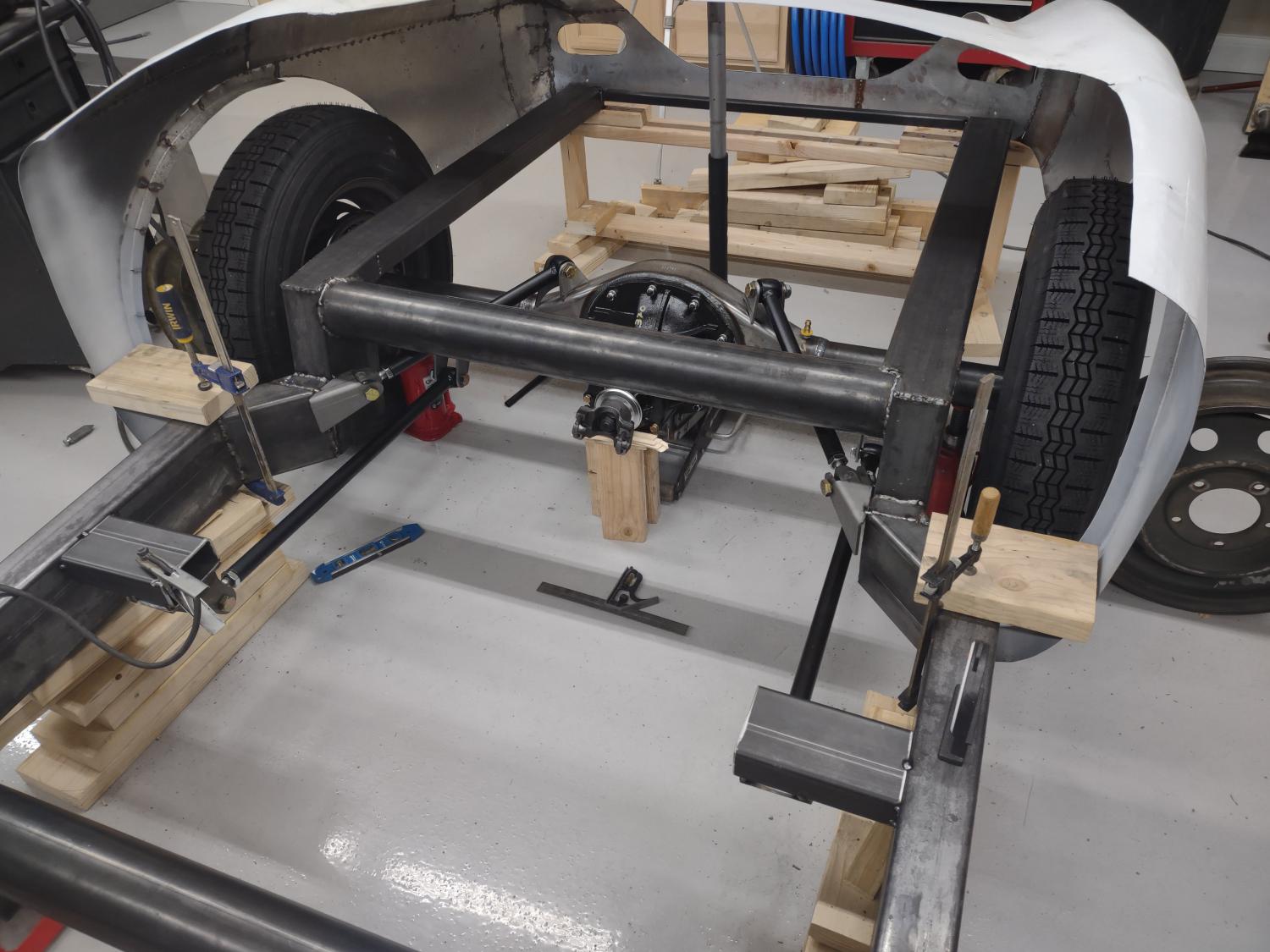
The plan started by positioning the rear in the frame rails and then verifying its square to the front. This involved me pseudo-mounting the tires to the axle since my bolt pattern was not correct. I measured front to back and also triangulated the measurement to make sure it was perfectly spare in the frame. In other words, the axle is not only on the same parallel with the front track, but its on the same longitude and not offset from the front wheels. Once I was confident that I had that I tilted the axle to set my initial pinion angle. The pinion of the rear needs to be on the same plane at the tilt of the motor. I set this using the intake manifold by measuring the angle of the carburetor mounting flanges. It shows about 5 degrees. Angling the rear up 5 degrees gets the pinion and engine centerline angle the same. Fine tuning happens with the links later.
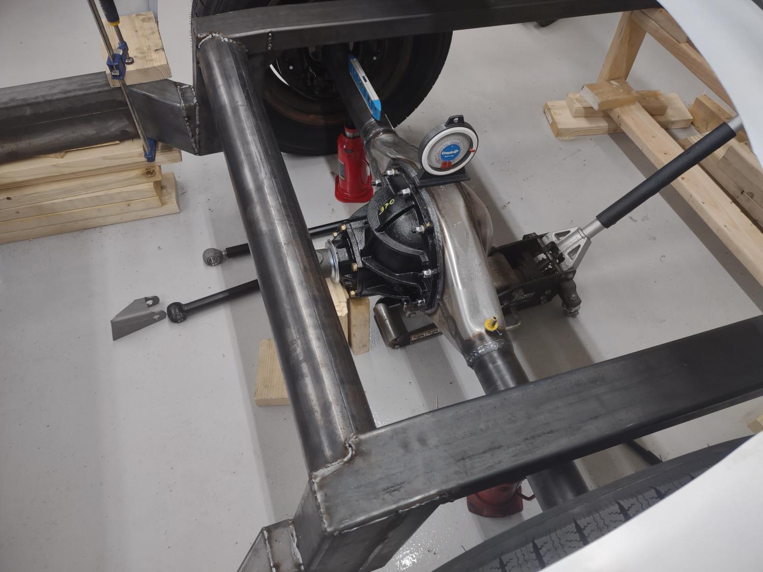
Once that was set it was time to set the bars in place. Initial mock up showed that the upper bars will work but might be pointing high, and lower bars needed to be hacked shorter. So, back online I go
.and then the sirens went off and arms flailed
Danger! DANGER Will Robinson!!!! Apparently you cant shorten the lower arms nor do you want the upper bars facing upwards. Something called Instant Center which is a percentage measured from a starting paint of 100% based on an imaginary measurement of the suspension linkage to a point where it intersects that is effectively the point of pivot for that set up.

I know, I thought the same thing
.HUH?

The fluorescent light bulb in my head displayed a weak ballast and was flickering. Well how in the heck does that get figured out and what the heck does that mean? Off to find people more smarter than me and luckily I was rewarded with an online calculator.
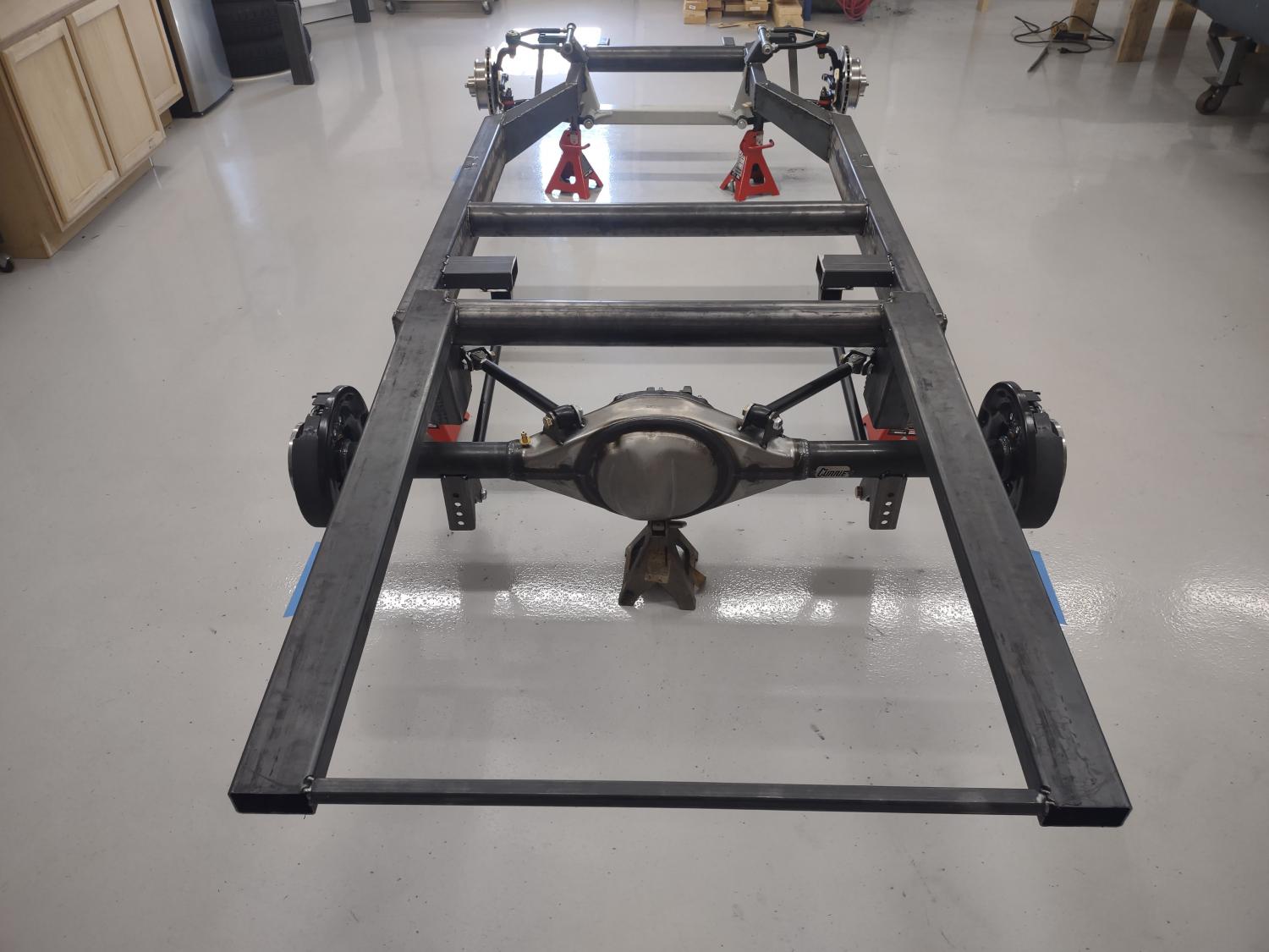
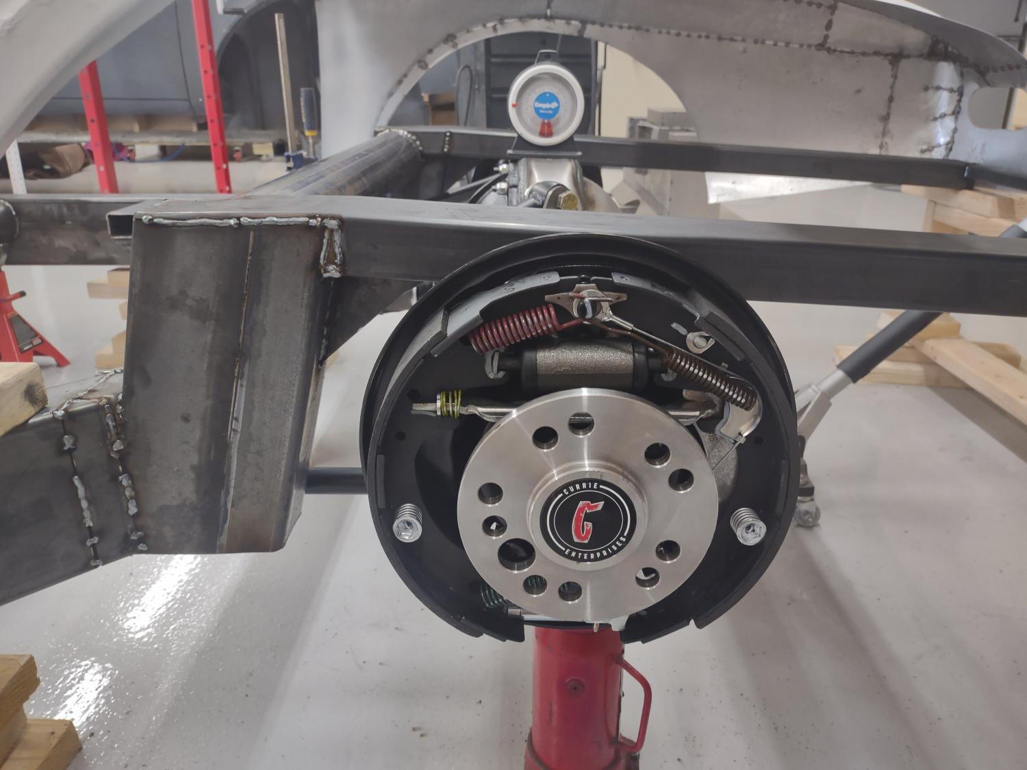
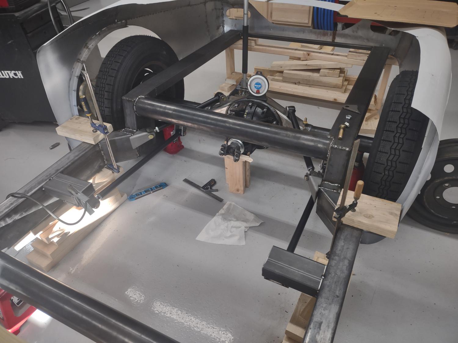
The light went on full bright after finding that calculator. No more flickering! I had to weld up mounts for the lower control arms, but the uppers seemed to fall in place. A test of the suspension through the movements with a jack and an angle gauge verified the pinion movement being acceptable through the suspension travel. The other things that need to be considered during the position of the brackets are the angles of the top arms to the longitudinal axis of the car and that all the mounts are parallel to each other as are the bars. Too shallow and angle and you dont have proper side play stability. Too steep and itll bind. About forty-five degrees, plus or minus a few, seems to be the best angle. Mine seemed to fall about at the forty degree mark. The left and right bars should be at the same angle and parallel to each other. In other words, one not higher set that the other. Theres one of those opticallical conclusions

happening on the rear since these Ferd 9 jobbies dont have a centered 3rd member which makes the bars appear to be at different angles since they mount a little offset from each other. The bars are the same height. The mounts are not. Finally, after all those angles are achieved and the suspension is verified it doesnt bind up, its welded in. I know
.PHEW!!!!!!!
So next up is floor pans, dash, steering column positioning along with the pedal quadrant and seat. So basically, I'm building the car multiple times and then one final time and then breaking it down for paint.
Yeah, I know... Another PHEW!!!

Cheers
Dave